PTW simulation: Three-winding transformers and harmonics
Let's suppose we have several different sources of harmonic currents on a distribution system; in this example we will take two variable frequency drives (VFDs) with 6-pulse rectifiers. These devices can be simulated easily in PTW and assigned harmonic profiles from a library of standard devices. If you know the full harmonic profile of your equipment, you can enter the data directly into the PTW component editor.
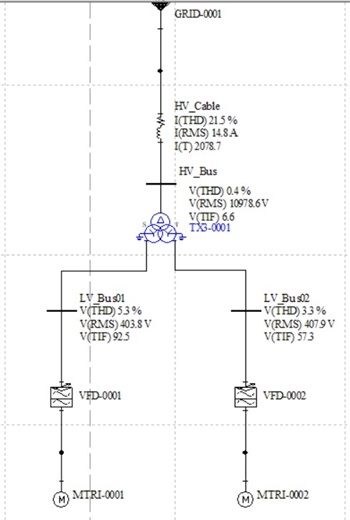
If we connect the rectifiers to the secondary and tertiary windings of a three-winding transformer as shown, all harmonics from the VFDs will be carried through to the HV (primary) side of the transformer, producing a total harmonic current distortion of 21.5%.
Triplet-order harmonics would not be carried through since this particular transformer has been modelled with a delta-wound primary; however in this case the VFDs produce no triplet-order harmonics.
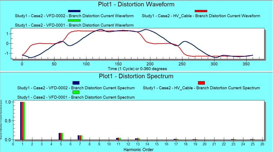
The waveform plot below shows the current passing through the two VFDs (marked "VFD-0001" and "VFD-0002") is identical and therefore the curves are superimposed over each other. The current through the HV (primary) side of the transformer (red line on the plot, below) has a phase shift compared to the VFD currents since the three phases are connected in delta whereas the secondary and tertiary windings are star-connected. There is some smoothing of the HV current waveform due to the inductance of the transformer, but the harmonic currents are the same in the HV system are essentially the same as those in the VFDs, as can be seen on the Distortion Spectrum plot below.
Triplet-order harmonics would not be carried through since this particular transformer has been modelled with a delta-wound primary; however in this case the VFDs produce no triplet-order harmonics.
The waveform plot below shows the current passing through the two VFDs (marked "VFD-0001" and "VFD-0002") is identical and therefore the curves are superimposed over each other. The current through the HV (primary) side of the transformer (red line on the plot, below) has a phase shift compared to the VFD currents since the three phases are connected in delta whereas the secondary and tertiary windings are star-connected. There is some smoothing of the HV current waveform due to the inductance of the transformer, but the harmonic currents are the same in the HV system are essentially the same as those in the VFDs, as can be seen on the Distortion Spectrum plot below.
Clearly this system is badly affected by harmonic currents and therefore connecting the HV system to a utility (grid) power supply would incur penalties for introducing harmonic "noise" on to the system.
We can improve this situation considerably without needing to add any harmonic filters. All we need to do is change the design of the three-winding transformer so that some of the harmonic currents caused by the two VFDs cancel each other out.
We can improve this situation considerably without needing to add any harmonic filters. All we need to do is change the design of the three-winding transformer so that some of the harmonic currents caused by the two VFDs cancel each other out.
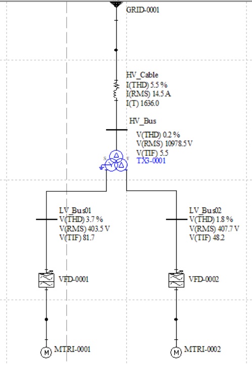
PTW allows us to simulate the effect of a different transformer configuration very easily. This new design (left) has the same delta-wound primary winding and star-wound secondary; the tertiary winding has now changed to a delta winding.
The effect of changing the winding connection of the transformer may be seen easily on the datablock on the single-line diagram on the left. The current THD in the HV side of the transformer has dropped from 21.5% to 5.5% even though no filtering has been applied. The reasons for this dramatic change are more obvious from the waveform and spectrum plots, below.
The current waveforms in the two VFDs (blue and green lines) still have the same profile but because the VFDs are connected to transformer windings with different vector groups, there is a phase difference between the two currents. The same waveform plot also shows the HV current (marked in red) which is now much closer to a sinusoid and shows less ripple.
Because the VFD harmonics have a phase difference between them, certain harmonics have cancelled each other out in the HV transformer winding.
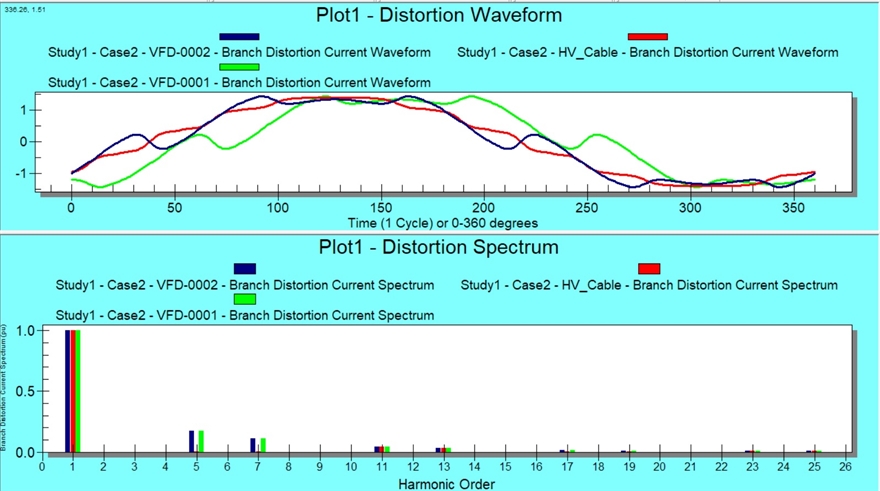
The distortion spectrum (above) shows how the 5th and 7th harmonics that are present in the VFDs have been virtually eliminated in the HV side of the transformer, simply by mutual cancellation. Therefore the overall THD in the HV system is much lower than before.
Allowing harmonics to cancel in this way is a useful tool for improving power quality without the need for investing in harmonic filters. The other advantage is that fewer harmonic currents are introduced into the earth system compared to harmonic filters; this can be important in cases where the earth connection is very weak.
Return to April newsletter.
These simulations were created using PTW's "Hi-Wave" module. Click here to find out more.