Time to Switch Gear? Switchgear failures and how to mitigate them
CEE presents the top five causes of switchgear failures and how to detect them. It may not always be possible to prevent switchgear failures but with help from CEE’s NP900 relays, emerging problems can be identified and mitigated as quickly as possible.
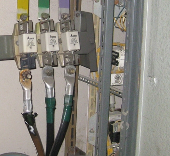
1. Loose connections
Loose electrical power connections create points of high resistance. These quickly lead to overheating and excessive currents (typically in only one phase ). Overheating has several different consequences; each one may cause the failure of switchgear or associated systems:
- Insulation failure (see later)
- Creeping or melting of conductors (most common with aluminium conductors)
- Fires of combustible materials within the switchgear enclosure
- Premature failure of fuses
The good news is that CEE’s NP900 relays have a special function specifically designed to monitor incoming power cable terminations to detect loose connections or insulation faults. It is known as the Cable End Differential Protection feature (ANSI code 87N ). The residual current of the three phase CTs is compared with the current through a CBCT on the incoming cable. Any difference between the two is interpreted as a leakage of current to earth somewhere on the incoming cable terminals; caused by either poor insulation or a loose connection. The function can be programmed to be resilient against small residual currents arising from imbalance between the three phase CTs, allowing the protection to be set very sensitively.
2. Insulation failures
The insulation of cables and conductors within switchgear compartments can fail due to overheating (as mentioned above); due to contamination causing “tracking” across the surface of insulators; due to voltage stresses created by small air gaps within insulation materials or simply due to mechanical damage. When insulation fails completely it will generally lead to phase-to-phase or phase-to-earth faults; some may develop into arcing faults.
Selected relays in the NP900 range are available with integrated arc detection. Place light sensors in vulnerable areas such as cable compartments and bus bar chambers to detect electric arcs; use these signals to initiate tripping of up-stream power sources to isolate the arc quickly (the NP900 relays detect arcs within 2ms). You can make your system resilient against spurious trips by including over-pressure sensors or prevent arc detectors from causing a trip unless there is a corresponding spike in current.
If you believe your power cables will be subject to a high degree of thermal stress, which could ultimately lead to insulation failure, also consider the NP900’s Cable Thermal Image function (ANSI code 49 ). Program your own thermal time constants to estimate incoming cables’ temperature based on the current through them. Set up to two alarm thresholds and one trip threshold; use these to trip the power supply and isolate any cables which are becoming dangerously hot.
If you believe your power cables will be subject to a high degree of thermal stress, which could ultimately lead to insulation failure, also consider the NP900’s Cable Thermal Image function (ANSI code 49 ). Program your own thermal time constants to estimate incoming cables’ temperature based on the current through them. Set up to two alarm thresholds and one trip threshold; use these to trip the power supply and isolate any cables which are becoming dangerously hot.
3. Water ingress
Although it is fairly obviously that large quantities of water within electrical distribution equipment can cause serious faults between phases or between phase and earth, it is less well known that even a small amount of moisture can lead to long-term damage. There are two principal mechanisms through which moisture can lead to damage: corrosion of conductors leading to loose or high-resistance connections (see above); or absorption of water by insulators due to voltage stress. Whilst anti-condensation heaters and climate control systems are often used to try to minimise moisture within electrical enclosures there are few systems to detect moisture ingress once it has occurred.
The NP900 relays have an innovative protection function to detect very short-duration earth faults which may be due to moisture ingress or self-extinguishing arcing faults within long cables. The Intermittent Earth Fault Detection feature (ANSI code 67NT) picks up directional earth faults which last only a fraction of a second at a time. Traditional directional earth fault protection relays often fail to pick up this type of fault since they use the RMS value of the zero-order voltage as the polarising quantity. Since intermittent earth faults cause only one or two voltage spikes, the fast Fourier-transform functions used to calculate RMS voltage are unable to accurately map the magnitude and angle of the voltage spike; hence the direction of the earth fault cannot be accurately measured. The NP900’s Intermittent Earth Fault Detection measures peak voltages and can therefore pick up directional earth faults consistently, regardless of their duration.
To track the condition of your switchgear over long periods of time, why not use the NP900’s built-in disturbance recorder to retain measured current and voltage data before, during and after faults have been detected? Customise the fault recorder to hold only the information you need; export the records from the NP900 relay in COMTRADE format and view them on CEE’s SMART9 software.
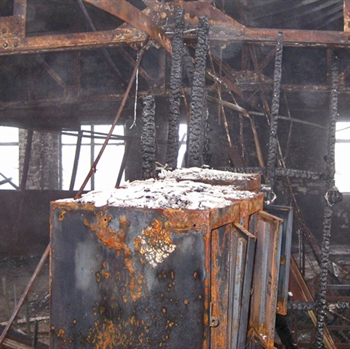
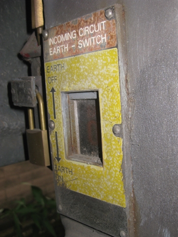
4. Racking breakers whilst closed
There are of course many forms of damage to electrical switchgear which may be attributed to human error; perhaps the most dangerous of these is attempting to connect a withdrawable circuit breaker to a system whilst the breaker is in the “closed” position. The worst-case example would be attempting to connect a live incomer to an earthed busbar system; thereby causing a three-phase-to-earth fault to flow through the withdrawable switchgear terminals. This type of fault will cause an electric arc of very high energy; enough to destroy equipment and cause fatal injury.
Mechanical interlocks have long been the main method of preventing users from racking a closed breaker onto a live system or accidental grounding. However, given the danger involved it is often advisable to have layers of back-up protection in the event that the interlocks fail.
As mentioned above, some NP900 relays may be supplied with built-in arc detection. The detection system can cover up to four different zones of protection, allowing one set of arc detectors in the circuit breaker chamber to send a trip signal to the up-stream protective device to isolate the fault.
Arc detectors, though very useful for limiting arc energy and reducing damage, will not prevent the situation from occurring in the first place. For this reason, the NP900’s internal logic system can be used to send a trip signal to the withdrawable circuit breaker when the limit switch is in the “withdrawn” position. The customisable HMI of the NP900 can also be used to display the status of other circuit breakers and earth switches in the distribution board. This is useful if users need to double-check the status of the equipment prior to racking circuit breakers in or out of service.
5. Faulty / poor earth fault protection
Solidly earthed electrical distribution systems are assumed to have very high earth fault currents and therefore earth-fault protective devices are set accordingly. Degradation of the earth connection can increase the impedance to earth and reduce the magnitude of earth fault currents below the point at which they would be detected, or increase the detection time considerably. Arcing faults between phase and earth can be especially dangerous in these circumstances since energy will continue to be released until the arc is extinguished.
Instantaneous overcurrent elements are sometimes used as the first line of defence against arcing faults. If the fault current is below the instantaneous threshold, other protection settings such as IDMT or low-set overcurrent elements may have to detect and isolate the arcing fault; these take longer. For this reason, PTW’s Arc Flash module will calculate arcing fault disconnection times both at the maximum arcing fault current and also at a lower current (typically 85% of maximum) to see which circumstance results in the highest release of energy.
The NP900 relays’ arc detection system can be used to detect and isolate arcing faults either in addition to, or instead of, traditional overcurrent protective devices, but what about non-arcing earth faults? CEE’s solution is the Multi-criteria Earth-fault protection feature of the NP900 series. This innovative and powerful protection function will automatically detect whether or not a system is earthed by analysing the symmetrical components of the currents and voltages. It is effectively a type of directional earth fault protection which can not only detect earth faults in earthed networks (fault current vector typically opposes zero-sequence voltage vector) but also in unearthed networks (fault current typically lags zero-sequence voltage by 90o). This function will continue to detect earth faults even if the earth connection is lost and then returned to service.
In Summary
There is no substitute for a well-planned and executed maintenance routine. Switchgear should be tested and maintained throughout its life to ensure correct operation. Why not use the “set timer” function on your NP900 relays to set annual maintenance reminders?