CEE Newsletter: What protects protective relays?
Happy New Year from CEE! Welcome to our new-format newsletter. As always, if you have any questions on power system protection, relays or systems studies then please contact us.
For our first article of the year, we would like to highlight an issue that was raised with us last year. Namely, what needs to be done to protect protective relays; their auxiliaries and associated control systems? This is a nuance of power system protection that is easily overlooked, yet a poor design can introduce unseen dangers or even compromise the integrity of the protection system itself. Naturally each power system will be different, so not all of these issues will affect your system. These are some of our thoughts and experiences. All the best for 2019!
-The Editor.
Auxiliary power for relays
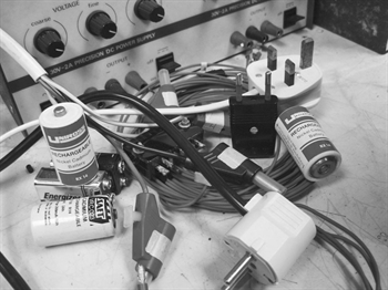
With the exception of electromechanical relays, or those powered via phase CTs, all protection relays require some form of external power supply to operate. All relays will have some form of tolerance on their auxiliary power supplies, outside of which the relay may be damaged or fail to operate correctly. How can this be prevented?
It has long been common practice to power several relays from the same circuit with no means to individually protect or isolate each relay. This is not necessarily a problem for maintenance since any protected equipment should be powered down prior to working on the relays themselves. The main problem with this strategy is that a fault on one relay’s power supply could cause the failure of every other power supply in that circuit.
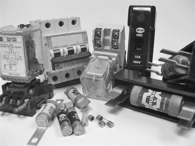
Overcurrent protection should be provided on auxiliary circuits but it should not be over-sensitive. Sensitive protection could lead to spurious trips during short-duration faults. The main purpose of the overcurrent protection should be to prevent current from being high enough to cause insulation damage to the auxiliary circuits (and therefore developing into a much more serious fault).
Overcurrent protection should be provided on auxiliary circuits but it should not be over-sensitive. Sensitive protection could lead to spurious trips during short-duration faults. The main purpose of the overcurrent protection should be to prevent current from being high enough to cause insulation damage to the auxiliary circuits (and therefore developing into a much more serious fault).
Under- and over-voltage protection on auxiliary circuits is less common. Most often this would be specified on systems with high criticality and would constitute only under/over-voltage alarms, not trips. This allows emerging problems to be investigated without the risk of spurious trips (for some short-duration faults many relays would simply reset as soon as the voltage came back within tolerance). In the most critical systems a voltage selector relay or uninterruptible power supply (UPS) system can switch to an alternate power supply in the event of failure of the first.
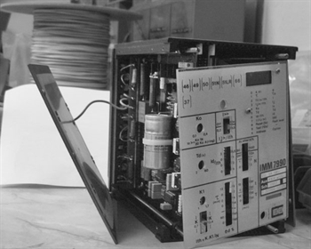
Wherever possible, system designers should make use of the watchdog contacts on protective relays. On the oldest relay types these will simply send an alarm signal whenever auxiliary power is lost. In more advanced relays such as CEE’s NP900 range, the watchdog also provides warnings based on internal diagnostics including over-temperature, processor failure or whilst some programming changes are being implemented. Watchdog circuits cannot prevent relay damage but they can warn of an emerging problem. There should always be a means to notify operational staff of a tripped auxiliary circuit to ensure that they do not expect protective devices to operate whilst they are out of service. This should be separate from trip circuit supervision systems which detect when circuit breakers fail to operate or have damaged trip circuits.
Wherever possible, system designers should make use of the watchdog contacts on protective relays. On the oldest relay types these will simply send an alarm signal whenever auxiliary power is lost. In more advanced relays such as CEE’s NP900 range, the watchdog also provides warnings based on internal diagnostics including over-temperature, processor failure or whilst some programming changes are being implemented. Watchdog circuits cannot prevent relay damage but they can warn of an emerging problem. There should always be a means to notify operational staff of a tripped auxiliary circuit to ensure that they do not expect protective devices to operate whilst they are out of service. This should be separate from trip circuit supervision systems which detect when circuit breakers fail to operate or have damaged trip circuits.
Auxiliary power for control circuits
Although becoming less and less common in new designs, hardwired control circuits incorporating electromechanical relay logic are still a feature of many protection schemes. As with the power for protection relays, it is generally better to provide only basic overcurrent protective devices such as miniature circuit breakers (MCBs) or fuses to avoid unnecessary tripping.
Attracted-armature auxiliary relays for control circuits have three major failure mechanisms;
- contact wear (contacts remain in open-circuit when they should be closed);
- coil failure (output contacts do not change state when the coil is energised);
- welding (contacts are stuck in their closed state).
Be very careful that there are no high-order harmonic currents present in your control circuits. As we highlighted in the April 2018 newsletter, harmonics can cause arcing across relay contacts and will ultimately cause your auxiliary relays to fail prematurely.
It is tempting to think that auxiliary circuits running on direct current (DC) only are immune to harmonic currents (which are, of course, AC). However earth leakage from AC circuits, or electromagnetic interference may still result in the presence of undetected alternating current in your direct current circuits. If possible, avoid using auxiliary relays to switch both AC and DC circuits in the same device (even if the currents and voltages involved are within the capability of that relay).
Current Transformers
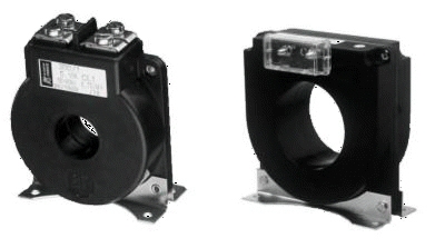
Current transformers (CTs) take no auxiliary power supply but produce a current signal proportional to the AC current in the main conductor passing through the CT. Excessively high currents in the main conductor will cause the CT to “saturate” (its output current is no longer proportional to the input) but will only cause damage in the most extreme circumstances. Furthermore, when there is current in the main conductor but the CT outputs are left open (un-connected), a potential difference will occur across the CT terminals which will discharge and cause damage. Therefore, fuses, overcurrent protective devices and switches are almost never used on CT outputs.
Because of the inherent danger of leaving CTs with un-connected outputs, measures are sometimes put in place to prevent this from occurring or to detect when CTs have been disconnected accidentally. In the case of CEE’s withdrawable “R-Case” relays and relays in the NP800 range, all CT connections are provided with a shorting link which automatically connects together the CT outputs when a relay is withdrawn from a panel. More advanced relays like the NP900 range have CT monitoring functions which passively detect damage to CTs by looking for large disparity between CT measurements on different phases or measurements well in excess of the CTs’ design capability.
Because of the inherent danger of leaving CTs with un-connected outputs, measures are sometimes put in place to prevent this from occurring or to detect when CTs have been disconnected accidentally. In the case of CEE’s withdrawable “R-Case” relays and relays in the NP800 range, all CT connections are provided with a shorting link which automatically connects together the CT outputs when a relay is withdrawn from a panel. More advanced relays like the NP900 range have CT monitoring functions which passively detect damage to CTs by looking for large disparity between CT measurements on different phases or measurements well in excess of the CTs’ design capability.
The manner in which CT outputs are connected to a protection relay is important, since reversed connections could make the measured currents appear to be flowing in the opposite direction. There is no easy means to protect against this other than good design, construction and maintenance. However, should one or more CTs be connected incorrectly to an NP900 relay there is a simple means to reverse the connections within the relay itself via the control screen. This eliminates the need to re-make connections after maintenance which could be difficult or time consuming to achieve.
Voltage Transformers
Like CTs, voltage transformers (VTs) take no auxiliary power supply. However, since they are connected to the main phase and / or neutral conductors, an internal fault could cause very high currents and almost certainly destroy the VT. For this reason, there are almost always overcurrent protective devices between the phase or neutral conductors and the VT inputs to limit the possible damage from a short circuit. Fuses are often preferable since they limit the energy passing through the VT during a fault.
VTs are designed to produce a voltage output signal proportional to the voltage between the main conductors. The output terminals may be left un-connected without causing damage, but short-circuits or low impedance connections between the VT outputs can produce extremely high currents when a voltage is applied to the inputs. Therefore, overcurrent protection is often fitted to VT outputs as well as the inputs.
Modern relays using VT inputs (including selected models of the NP900 range) can detect the failure of VTs in order to raise an alarm, trip a power supply or inhibit certain functions such as synchronisation checking which rely on VT signals. Where the VT overcurrent protective devices are MCBs with auxiliary contacts, some protection relays can interrogate the contact to detect when one or more of the MCBs has tripped. Relays in the NP900 range have an additional mechanism for detecting VT failure; they monitor the magnitude of the measured voltage and raise an alarm when voltages are very low (but non-zero) or excessively high.
Communications Networks
Sharing information between protective relays and a central operator console or SCADA system is not a new concept. Older systems such as current-loop networks were neither fast nor reliable enough to send or receive trip signals and could really only be used for sharing system status information. For the purposes of protecting the communications loop, the system would be resilient against one or more networked devices going offline due to maintenance or loss of power; however breaking the current loop itself would cease all communications. The current loop had to be shielded against electromagnetic interference and protected against contact with high-current conductors which could damage every device on the network.
More modern fibre optic networks need no screening since they are inherently non-conductive; the only protection fibres require is against mechanical damage. To improve the resilience of the system, a PRP network design may be employed. In this design, all communications fibres between protective relays and other devices are duplicated; the two sets of fibres should ideally follow completely different routes.
More modern fibre optic networks need no screening since they are inherently non-conductive; the only protection fibres require is against mechanical damage. To improve the resilience of the system, a PRP network design may be employed. In this design, all communications fibres between protective relays and other devices are duplicated; the two sets of fibres should ideally follow completely different routes.
CEE’s NP900 range of relays are available with communication cards that have two sets of fibre optic communication ports for precisely this reason. The two sets of fibres ensure that a problem causing damage to one fibre will not affect the other and therefore the signals may continue to pass between devices. When both fibres are fully functional, each networked device is programmed to reject any duplicate messages (one message received from one fibre; a second message from the other). These added layers of security allow communications networks to perform critical functions including sending “trip” signals and raising alarms. In terms of protecting the network hardware itself, it is recommended that any network switches or communications devices are powered from a UPS system to make sure that they continue to operate in an emergency. For PRP networks, each of the two independent fibre loops can be cross-connected to two network switches. Therefore, the failure of one switch will allow both fibre loops to continue to operate and vice versa.
In Summary...
- There is no “catch-all” solution to shielding your protective relays from damage. At the earliest stages of design, a decision must be made as to how critical your protective system is and how many layers of backup protection you need to employ.
- Always consider the case where a protective device has failed to operate. Would your power network continue to operate if one or more protective relays had failed?
- If one relay acts as back-up to another, make sure they are on separate auxiliary power supply circuits!
- Protecting your auxiliary circuits from mechanical damage is always a good thing to do.
- Segregating control circuits from main power conductors is advisable, in as far as is practical (naturally, CTs and VTs must be in the same compartment as the main conductors!).
- Provide operator alarms in the event of failure of one or more protective relays