CEE Newsletter: Getting the most out of your ISA test set
Dear Customer,
For the last newsletter of 2019 we would like to focus on relay testing. Specifically, on using our popular “DRTS” models of secondary injection test sets. No doubt you already have a lot of experience testing protection relays on your system, so rather than giving you a step-by-step guide I would like to share with you some tips and tricks for making your test processes more efficient. If there’s something else that you are unsure of you are welcome to get in touch.
For the last newsletter of 2019 we would like to focus on relay testing. Specifically, on using our popular “DRTS” models of secondary injection test sets. No doubt you already have a lot of experience testing protection relays on your system, so rather than giving you a step-by-step guide I would like to share with you some tips and tricks for making your test processes more efficient. If there’s something else that you are unsure of you are welcome to get in touch.
I need more DC outputs
Many test sets have a built-in DC output as standard. Nominally this is intended for providing auxiliary power to protection relays when bench testing, but a DC supply can also be useful for simulating a digital input signal or mimicking a circuit breaker trip circuit for TCS relays. In these circumstances you might need more than one DC output to run your test.
Option 1: Change the test frequency
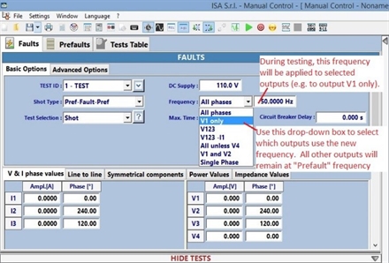
Where only DC voltage or current outputs are required, the simplest test procedure is to set the system frequency to 0Hz. By default, this applies to all current and voltage outputs from the test set. The voltage outputs can then be used to provide DC signals for the relay under test. Voltage outputs set to 0Hz will experience a small amount of ripple compared to the standard DC output; this might be enough to confuse relays with digital inputs that have sensitive on/off voltage thresholds.
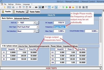
If some AC and some DC outputs are required, it is possible to change the frequency of only selected voltage outputs and leave the other current and voltage outputs at the pre-fault test frequency.
Where only DC voltage or current outputs are required, the simplest test procedure is to set the system frequency to 0Hz. By default, this applies to all current and voltage outputs from the test set. The voltage outputs can then be used to provide DC signals for the relay under test. Voltage outputs set to 0Hz will experience a small amount of ripple compared to the standard DC output; this might be enough to confuse relays with digital inputs that have sensitive on/off voltage thresholds.
If some AC and some DC outputs are required, it is possible to change the frequency of only selected voltage outputs and leave the other current and voltage outputs at the pre-fault test frequency.
Note that:
Option 2: Make use of the binary outputs
- All current and voltage outputs (except the separate DC power supply) will produce AC during the pre-fault stage, set at the pre-fault frequency (unless this is also 0Hz). This will happen regardless of whether specified outputs produce DC during the fault stage.
- Any current or voltage outputs which are not set to 0Hz during the fault stage will continue to operate at the pre-fault frequency.
Option 2: Make use of the binary outputs
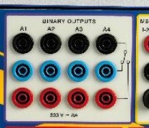
Test sets in the DRTS range are equipped with binary outputs. These are change-over contacts which may be programmed to change state at the start of a test or after a time delay. Why not connect the DC power supply output to one or more of these binary outputs to simulate DC signals to the relay?
(Left) Binary outputs provide change-over relay contacts which may be programmed to change state during a secondary injection test.
Simulating Unbalance and Zero-sequence currents
It is fairly straightforward to test a three-phase current unbalance relay by injecting current into only two phases. However, a multi-function relay might also have a trip setting for zero-sequence currents calculated from the residual of the three phase inputs. Therefore injecting only one or two phases could trip either function (depending on the programmed trip time and current). What is the best way to test these two functions without one interfering with the other?
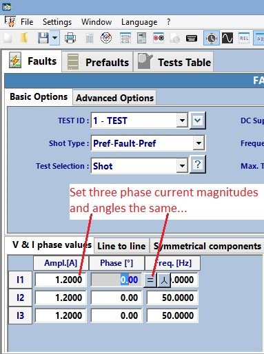
Choosing test settings for zero-sequence tests it quite simple. Set the magnitude and phase angle of all three injected currents to the same value. This will produce a resultant zero-sequence current without any positive or negative sequence components. The zero-sequence magnitude is the same as the sum of the magnitudes of the three injected phase currents – therefore it is simple to test a precise trip threshold.
Choosing test settings for zero-sequence tests it quite simple. Set the magnitude and phase angle of all three injected currents to the same value. This will produce a resultant zero-sequence current without any positive or negative sequence components. The zero-sequence magnitude is the same as the sum of the magnitudes of the three injected phase currents – therefore it is simple to test a precise trip threshold.
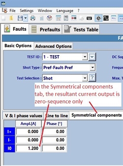
(Left)
Screenshot from TDMS.
Choosing parameters for a zero-sequence overcurrent test in the V & I phase values tab.
(Right)
Screenshot from TDMS.
The chosen parameters can also be set in the Symmetrical components tab. This is merely a different way of representing the same information; the current injected by the test set will be exactly the same.
Changes made in one tab will be updated automatically in the other tabs
Screenshot from TDMS.
Choosing parameters for a zero-sequence overcurrent test in the V & I phase values tab.
(Right)
Screenshot from TDMS.
The chosen parameters can also be set in the Symmetrical components tab. This is merely a different way of representing the same information; the current injected by the test set will be exactly the same.
Changes made in one tab will be updated automatically in the other tabs
Choosing test settings for unbalance tests is much harder, since the unbalance trip setting is often based on the negative-sequence currents being a percentage of the positive-sequence currents. Therefore, the test requires injection of a specific ratio of positive and negative-sequence currents with no zero-sequence currents. The good news is that our TDMS software has a feature which will calculate the positive, negative and zero-sequence currents for you. It can also be used to back-calculate the magnitude and angle of the required phase currents based on positive, negative and zero-sequence inputs.
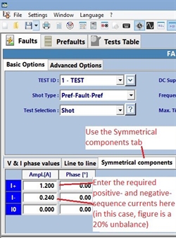
(Left)
Screenshot from TDMS.
Choosing parameters for an unbalance test in the Symmetrical components tab.
In this example, the I0 (zero-sequence) current has been set to 0.000A to ensure that there are no spurious trips caused by the relay's zero-sequence element.
(Right)
Screenshot from TDMS.
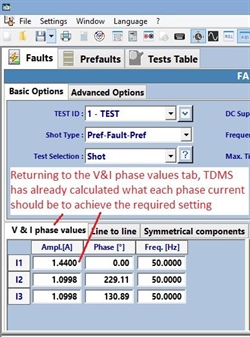
The chosen parameters can now be viewed in the V & I phase values tab. This is merely a different way of representing the same information; the current injected by the test set will be exactly the same.
Screenshot from TDMS.
Choosing parameters for an unbalance test in the Symmetrical components tab.
In this example, the I0 (zero-sequence) current has been set to 0.000A to ensure that there are no spurious trips caused by the relay's zero-sequence element.
(Right)
Screenshot from TDMS.
The chosen parameters can now be viewed in the V & I phase values tab. This is merely a different way of representing the same information; the current injected by the test set will be exactly the same.
Quickly choose test settings for over/under-power and over/under-impedance relays
The TDMS software can not only express current and voltage test settings in terms of their positive, negative and zero-sequence components; it can also express these parameters in terms of injected power or impedance.
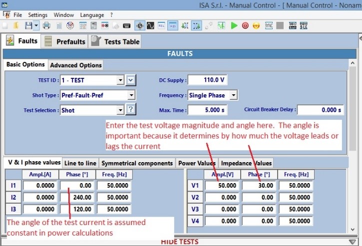
To calculate the current required for testing at a particular power, first open the “V&I phase values” tab and enter the phase voltage magnitude and angle.
To calculate the current required for testing at a particular power, first open the “V&I phase values” tab and enter the phase voltage magnitude and angle.
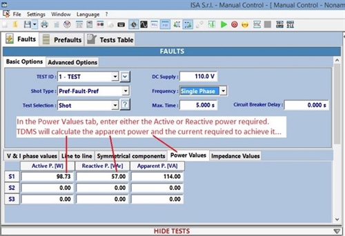
Next, move to the “Power Values” tab and enter either the active or reactive power required. TDMS will assume that the voltage and current angles are fixed, and therefore calculates the current and the other power values accordingly.
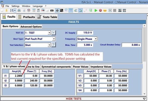
In this last screenshot, we see what current values have been calculated by TDMS. This is merely another way of representing the same information as the previous screen.
TDMS calculates the voltages and currents for a specific impedance in a slightly different manner. In the “Impedance Values” tab, first enter the parameters of the network on which the relay operates. See the screenshot on the right.
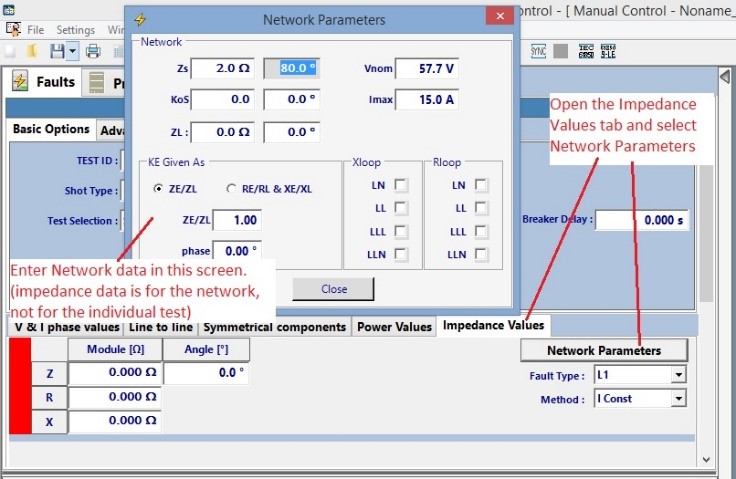
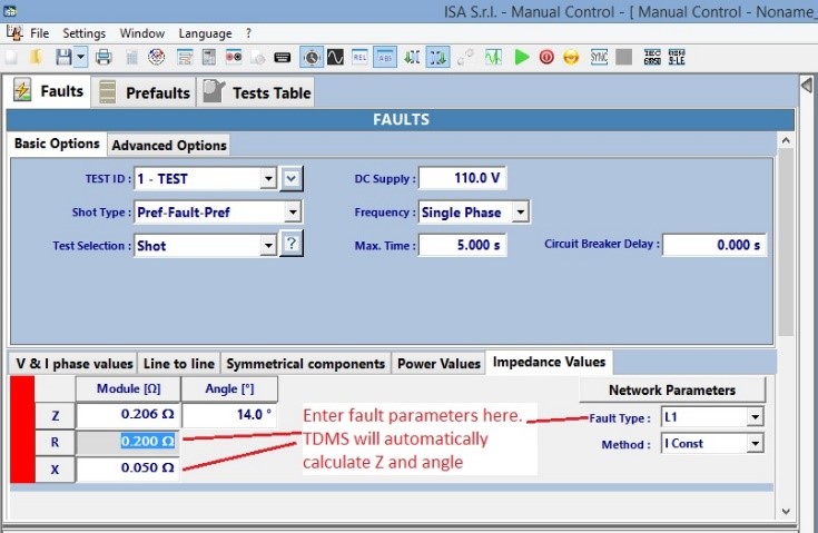
Next, select the type of fault to be simulated and enter the required test impedance. See the screenshot on the left.
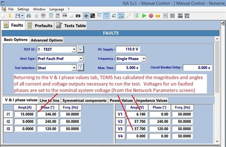
As with other tests, reverting back to the “V&I phase values” tab will display the magnitudes and phase angles of the currents and voltages TDMS is proposing to inject. See the screenshot on the right.
Test plans and past results
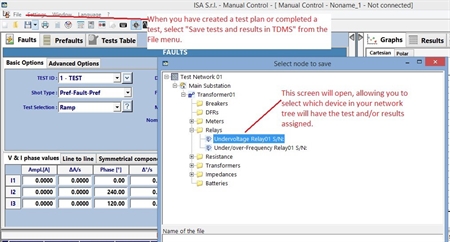
You are no doubt already aware that tests performed in the Manual Control screen can be saved (either with or without the results) to separate files for later retrieval. Tests and results can also be saved within the TDMS program, assigned to a virtual device in the Network Tree.
The Network Tree is a representation of all the relays and other components in your network; it can be edited in the Network Tree tab on the main TDMS screen.
The Network Tree is a representation of all the relays and other components in your network; it can be edited in the Network Tree tab on the main TDMS screen.
To use this feature of the TDMS software, first populate the Network Tree with virtual components representing the main elements of your electrical network. Any testing performed using TDMS (for example, secondary injection tests using the Manual Control program) can be recorded and linked to these virtual components in the Network Tree.
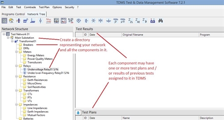
(above, left) The Network Tree in TDMS can be used to create a virtual model of your network
(above, right) In the Manual Control screen, any tests and results can be saved to the Network Tree for later retrieval
Any test plans saved to the Network Tree can be opened later to either refine the plan or repeat the tests. New test results can also be saved to the Network Tree.
Now that you have saved your test plan, there are a few refinements you can add to your test plans to make future testing easier.
Now that you have saved your test plan, there are a few refinements you can add to your test plans to make future testing easier.
Add a Notes page to the test plan
In the manual control screen, select File and then Notes to the Test. This is a good place to record information such as
- How the DRTS should be connected to the equipment under test
- What sort of results the test engineer should expect in each step
- Relay settings and other useful background information
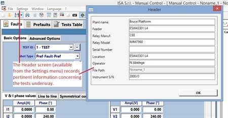
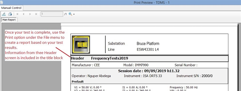
Note that there is also a separate screen named “Header”, accessed via the Settings menu.
Information recorded here (including relay type, serial number, sub-station etc.) will be used to identify the test report when the results are printed.
(Left) This is where Header information is recorded in TDMS.
(Below) This is how the information appears when it is used to print a test report.
Information recorded here (including relay type, serial number, sub-station etc.) will be used to identify the test report when the results are printed.
(Left) This is where Header information is recorded in TDMS.
(Below) This is how the information appears when it is used to print a test report.
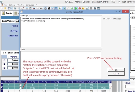
Add user notes
If notes or instructions are required during testing, for example prompting a user to change the DRTS connections prior to commencing the next test, these can be added as follows:
- Select the test row to which you would like to apply the note
- Right-click and select Define Instruction.
- In the screen which appears there are two sections. The Message section allows you to enter a user message which will be displayed prior to the start of the selected test row (the Show This Message check box must be ticked). The Notes section does not display when the test is running. It is more useful for background information such as a record of why particular test settings were chosen.
Display only the information you require
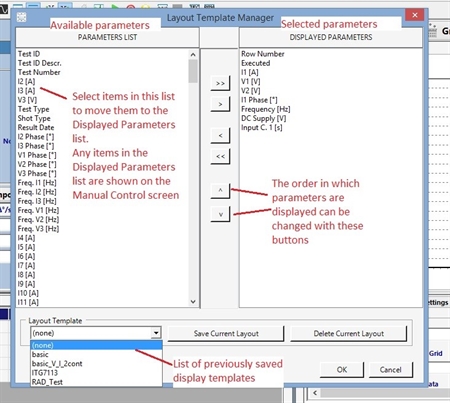
By default, the table of results in the Manual Control screen will show many columns representing different input or measured quantities. Some of this data may not be relevant to the test at hand (such as outputs which are not used, system frequencies which do not change etc.).
Different data to display can be chosen by right-clicking anywhere on the test plan and selecting Modify Columns Layout. This screen will allow you to choose from available parameters on the left and add or remove them from the displayed parameters on the right. The order in which columns are displayed may also be changed.
If the column layout is particularly useful for future tests you can even save it independently of the tests and results. Use the Save Current Layout button on the Modify Columns Layout screen.
Note that even if un-wanted columns are removed from the display, the information will still be saved along with the test results. Therefore reinstating the column of data (for example, the trip time of input contact C1 using parameter “Input C.1 [s]”) will display the measurements for that parameter.
Use formulae to process results
Sometimes simply recording a trip time or the final current injected before a trip won’t be enough. Your test may require some processing of the results, for example if the difference between two injected currents must fall within a certain range for a relay to pass the test. A test engineer can of course look at the results on the screen and perform the calculation themselves, but this could lead to some errors if the same procedure must be repeated many times over.
TDMS has the answer. You can define up to six custom formulae in your test plan, each of which can be displayed in the results table as a column of data. Let’s take the example given above and see how it can be applied to a test.
I want to find the absolute value (positive or negative) of the difference between test currents I3 and I1 so that I can decide if the result is acceptable.
- First, I go to the File menu and select Manage Formulas and Custom Fields
- In the Formula Editor tab, I can start creating a formula in one of the six available rows. The available Fields, Functions etc. are listed at the bottom of the screen and can be used to build an expression – alternatively I can simply type the expression I wish to use.
- The Check button lets me verify that the formula is a valid expression before implementing it.
- The + button lets me save the formula so that I can apply it to any other test plan. This is saved to TDMS itself so the formula can be re-used in many different tests.
- The text box called Labels allows me to choose a name for the formula which will then appear on the results table of TDMS.
- To display the result of the formula I now click OK in the Formula Editor, then select Modify Columns Layout from the File menu.
- The formula is added to the results table in the same way as any other measured quantity. It is named “Formula 1” by default, unless I chose a new name in the Labels text box of the Formula Editor.
- The Formula Editor has a separate field for the Pass/Fail criterion. Expressions can be entered here in the same way as any custom formula except the result must always be either True or False.
- As with a custom formula, I must now add this field to the results table using the Modify Columns Layout menu. Tests which have passed the criterion will be labelled “-1” and tests which have failed will be labelled “0”.
AC auxiliary power supplies
In the UK, most of the older designs of switchboards used DC power supplies to power protection relays and other control devices. These had the advantage that they were easy to provide with battery backups in case the main power supply was lost. Many modern relays, including versions of the NP900 series of relays, are capable of taking power supplies at either AC or DC over a range of voltages. In other words, for the vast majority of secondary injection tests you would expect to be using the DRTS test set’s built-in DC output as a source of auxiliary power for the relay under test. However, there are some relay models which are built to take an AC power source only. In such cases, there are various options for powering the relay while it is being tested:
- Use a mains power supply. This option will work only if the relay under test has a power supply input rated at 230VAC (or at whichever AC voltage is locally available). Attempting to power the relay outside of its acceptable range could be dangerous.
- Test the relay in-situ. If it is possible to maintain the auxiliary power supply within the switchboard, the relay could be powered from its usual source. This also depends on the accessibility of relay terminals for secondary injection testing – consider installing test blocks in your switchboard. Ensure that testing the relay in situ will not cause spurious trips or impede safety systems.
- Use a spare voltage output on the DRTS test set. If one or more voltage outputs are not required for testing, they may be used as a power source for the relay under test. This can be a very useful method of bench testing a relay, but there are some considerations which must be made:
Powering a relay using AC voltage outputs:
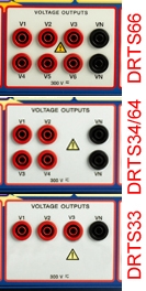
Test sets of type DRTS3, DRTS33, DRTS34 and DRTS64 have either three or four AC voltage outputs depending on the model. However, the neutral point of all of these voltage outputs is common via terminal(s) VN. Therefore, connecting the power input of the relay between two phase outputs (for example V1-V2) while injecting test voltage between phase and neutral (for example V3-VN) is not advised. Doing so causes the voltage used to power the relay to create a residual voltage on the VN terminal; this changes the test voltage applied across terminals V3-VN. It is generally better to apply both power and test voltages between phase and neutral to remove this imbalance. In the case of the DRTS66, the voltage outputs are in two groups (V1-V3 and V4-V6) each with its own neutral point. Therefore it is advisable to apply power to the relay via a different voltage group than the test voltage(s).
Test sets of type DRTS3, DRTS33, DRTS34 and DRTS64 have either three or four AC voltage outputs depending on the model. However, the neutral point of all of these voltage outputs is common via terminal(s) VN. Therefore, connecting the power input of the relay between two phase outputs (for example V1-V2) while injecting test voltage between phase and neutral (for example V3-VN) is not advised. Doing so causes the voltage used to power the relay to create a residual voltage on the VN terminal; this changes the test voltage applied across terminals V3-VN. It is generally better to apply both power and test voltages between phase and neutral to remove this imbalance. In the case of the DRTS66, the voltage outputs are in two groups (V1-V3 and V4-V6) each with its own neutral point. Therefore it is advisable to apply power to the relay via a different voltage group than the test voltage(s).
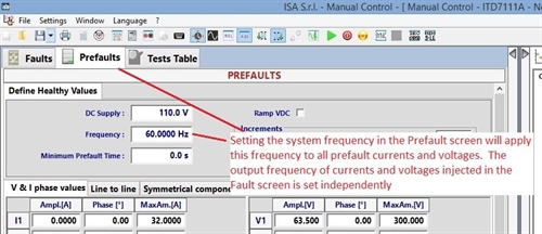
Be aware of system frequency. Generally a relay which is designed to operate on a 50Hz system will also have an AC power supply rated at 50Hz. Over/under-frequency relays will require the test frequency to change during secondary injection testing. Therefore, care must be taken that the voltage output which is used to power the relay remains at a steady frequency during this time. As noted in the “Option 1: Change Test Frequency” section above, changes in frequency during testing can be applied to all current and voltage outputs, selected voltages or each output individually.
Do you need even more functionality?
So far we have only looked at running tests in the TDMS program using the “Manual Control” screen. However, there are more features you can unlock by preparing programs in the Advanced Test Plan Editor. Programs created in this way can perform additional tasks, such as calculating subsequent test parameters based on previous test results.
If you would like to know more, why not ask us about training or custom relay testing programs written on your behalf.
If you would like to know more, why not ask us about training or custom relay testing programs written on your behalf.
- DRTS secondary injection test sets are versatile devices which can perform many tasks beyond simply injecting test voltages and currents.
- CEE Relays Ltd can supply these and other test sets according to your requirements.
- There are many other aspects to relay testing which have not been covered in this article.
- The TDMS software package has many other tools and sub-programs which allow you to operate your DRTS test set at its full potential. These include automatic test schemes for specific functions such as Synchro-check (ANSI 25) and Differential protection (ANSI 87).
- Please contact us if you have any particular requirements or a question that has not been covered here.
In Summary