

CEE Relays Ltd
|
|
Tel:
+44 1753 576477
Fax: +44 1753 825661
Learn More About Integrated Arc Detection
CEE's latest AP900 range of arc detection relays uses various types of sensors to detect arcs. Some of the digital multi-function relays in CEE's NP900 range can also be manufactured with built-in Arc Detection units. This page is intended to provide an overview of how they work, what the different technologies are, and what benefits they can offer your company.

What is an Arc?
Electric arcs are dangerous releases of energy which occur when an electrical fault is not properly interrupted. Most modern switchgear is designed to contain, quench or prevent an arc from forming but arcs may still occur. This may be due to improper use of switchgear, damage to part of the distribution system or overloads exceeding the system’s design current interrupting capacity.
Electric arcs are characterised by:
Electric arcs are characterised by:
- Very bright, intense light
- Pressure waves, akin to an explosion in extreme cases
- Intense, localised heat
- Noises ranging from "fizzing" or "popping" sounds to deafening explosions
- Distortion in the voltage waveform of the power supply feeding the arc
- Excessive current draw
Arc Detection Technologies
In theory, any of the six characteristics of electric arcs listed above could be used as a means of identifying when and where an arc is taking place. To be absolutely certain that an arc is in progress, it may be advisable to use a combination of different types of sensor in your detection system. The following are technologies employed by CEE's range of arc detectors for the AP900 arc detector relays and NP900 relays:
Light sensors
Detect the light produced by an arc fault. They may be in the form of point-sensors to detect light in a specific place within a switchgear compartment or fibre optic loop sensors which detect light anywhere along their length.
Point-sensors are calibrated to only send a "trip" signal when a certain minimum intensity of light has been detected. They are non-latching. See the "Point sensors" section below for the details.
Light point-sensors are the primary arc detection mechanism used by NP900 relays.
Some AP900 arc detection relays may employ fibre optic loop sensors. These are useful for protecting large compartments such as busbar chambers because they can detect light coming from any direction over a wide area. See the "Fibre Optic Loop Sensors" section below for details.
Pressure sensors
Detect the pressure wave produced during an arc. The type supplied by CEE is always combined with a light sensor such that the sensor will only send a "trip" signal if it detects both light and overpressure at the same time. Pressure sensors can be a good way of reducing spurious trips, since there is rarely any source of pressure within the switchgear other than an arc.
The detection time of pressure sensors depends heavily on the mechanical design of the switchgear compartment being protected. For a small compartment, using pressure-and-light sensors typically adds 5ms to the arc detection time over and above the response time of a light-only sensor. Pressure sensors are not considered appropriate for large, unsegregated switchgear panels or for compartments which are not totally enclosed.
Current sensors
NP900 relays fitted with Arc Detection units do not employ dedicated current sensors for detecting arcs. Instead, those relays with inbuilt overcurrent protection can be programmed to ignore inputs from light sensors (or light-and-pressure sensors) unless they detect a simultaneous increase in the current drawn. This helps to avoid spurious trips caused by light from other sources (inspection lamps, camera flashes or brief arcs across contactor terminals). It can also be used as a form of discrimination; if several current sources pass through a compartment where light is detected, only those experiencing high currents will be isolated. Since the relay must detect both light and overcurrent at the same time, the operating time will be slightly longer (see the "Benefits of Arc Detection" section below for details).
Two overcurrent settings are available in the NP900 arc detection module: phase overcurrent and residual overcurrent. These may be set to different thresholds as appropriate.
Similarly, some AP900 relays have inputs for phase CTs and earth fault CTs which may be used to desensitise the arc detection system to spurious trips.
Arc Detection Modules (NP900 series)
Selected NP900 relays can be specified with an Arc Detection module which has 4 sensor input channels. Up to three sensors can be connected in parallel, allowing the module to accept a maximum of 12 sensors in total. The four different channels allow you to build a system with up to four different zones of protection if required.
Below are some details about the individual arc detection components. Arc detection schemes which incorporate overcurrent measurements will use the NP900's CTs (where applicable). However, overcurrent settings associated with arc detection are independent of any overcurrent-only settings (instantaneous, definite time or IDMT) programmed into the relay.
Below are some details about the individual arc detection components. Arc detection schemes which incorporate overcurrent measurements will use the NP900's CTs (where applicable). However, overcurrent settings associated with arc detection are independent of any overcurrent-only settings (instantaneous, definite time or IDMT) programmed into the relay.
Arc Detection Module
|
Sensor inputs |
4 (twisted pairs) | May be used to connect light sensors or combined light-and-pressure sensors |
| Binary inputs | 1 (24VDC) |
Semiconductor input, may be used for discrimination with other arc detection modules |
| Binary outputs | 2 (normally open) |
High-speed semiconductor outputs (250VDC withstand, 2A continuous carry). It is recommended that these are used for signalling only; the NP900 trip output should be used to initiate trips. |
Point Sensors (NP900 and AP900 series)
Light Sensors
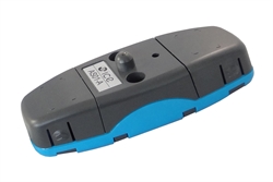
(Pictured, right): AS01-A Point sensor for light. The light detector is the projection in the middle of the unit.
|
Light detection radius |
180o | Sensor should be mounted facing the most likely source of an arc (terminals and cable joints are recommended). |
| Maximum cable length | 200m | Maximum cable length per sensor. Sensors connected in parallel across the same Arc Detection input can each have cables up to 200m long. |
| Light intensity threshold | 8000 lux |
This approximates to the light intensity of a phase-earth arc on a 200A system. |
Light sensors have normally open semiconductor outputs which are non-latching. However, when correctly connected to the Arc Detection module on an NP900 relay or AP900 arc detection relay, the relay will store a record of any light detection events in non-volatile memory.
Light and Pressure Sensors
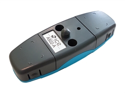
(Pictured, right): AS02-A Point sensor for light and pressure. The light detector is the projection in the middle of the unit; the pressure sensor is within the casing.
|
Light detection radius |
180o | Sensor should be mounted facing the most likely source of an arc (terminals and cable joints are recommended). |
| Maximum cable length | 200m | Maximum cable length per sensor. Sensors connected in parallel across the same Arc Detection input can each have cables up to 200m long. |
| Light intensity threshold | 8000 lux |
This approximates to the light intensity of a phase-earth arc on a 200A system. |
Combined sensors have normally open semiconductor outputs which are non-latching. They must detect both a sufficiently strong light source and a sudden increase in pressure at the same time before sending a signal to the NP900 relay or AP900 arc detection relay.
Fibre Optic Loop Sensors (AP900 only)
Plastic Fibre Optic Sensors
|
Light detection radius |
360o | Fibre can detect light anywhere along its length |
| Maximum fibre length | 40m | Note that the fibre must form a continuous loop, starting and finishing in the same AP900 arc detection relay. |
| Minimum fibre bending radius | 5cm | Tighter radii will damage the fibre. Avoid sharp edges, friction or moving parts to prevent damage. |
| Light intensity threshold | 8000 lux |
This approximates to the light intensity of a phase-earth arc on a 200A system. |
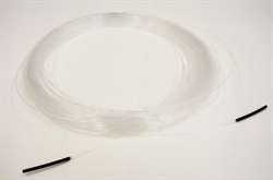
(Pictured left): AS06 Plastic fibre loop sensor.
Plastic fibre loops are inexpensive but their maximum length is shorter than the glass fibre equivalent due to attenuation of light within the fibre.
Plastic fibre loops are inexpensive but their maximum length is shorter than the glass fibre equivalent due to attenuation of light within the fibre.
Glass Fibre Optic Sensors
|
Light detection radius |
360o | Fibre can detect light anywhere along its length |
| Maximum fibre length | 50m | Note that the fibre must form a continuous loop, starting and finishing in the same AP900 arc detection relay. |
| Minimum fibre bending radius | 1cm | Tighter radii will damage the fibre. Avoid sharp edges, friction or moving parts to prevent damage. |
| Light intensity threshold | 8000 lux |
This approximates to the light intensity of a phase-earth arc on a 200A system. |
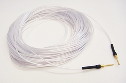
(Pictured left): AS07 Glass fibre loop sensor.
Glass fibre loops are better at transmitting light and can therefore be longer than their plastic equivalents. The coated glass design of the AS07 sensor allows it to be installed with a relatively tight bending radius compared to its all-plastic equivalent (AS06).
Glass fibre loops are better at transmitting light and can therefore be longer than their plastic equivalents. The coated glass design of the AS07 sensor allows it to be installed with a relatively tight bending radius compared to its all-plastic equivalent (AS06).
Benefits of Arc Detection
Arc detection systems can react much faster than traditional overcurrent protection systems since they do not need to discriminate with upstream protective devices or allow short-duration overcurrent situations such as motor starts or energising transformers. Put simply, intense light or pressure waves within switchgear are generally "bad" situations requiring an immediate trip.
Very short trip times are useful since they limit the amount of energy released during an arc. Typical trip times for arc detection on NP900 relays are shown below (these exclude circuit breaker operating times, which will depend upon the make and model):
Are you unsure of the potential arc energy that could be released by your system? Consider the Power*Tools for Windows modelling software or ask CEE for an arc flash study.
Very short trip times are useful since they limit the amount of energy released during an arc. Typical trip times for arc detection on NP900 relays are shown below (these exclude circuit breaker operating times, which will depend upon the make and model):
- Light only typically 11ms (up to 18ms max)
- Light and overcurrent 17ms (up to 22.5ms max; assumes overcurrent has been set to the recommended threshold of 1.5x nominal phase current)
- If light-and-pressure sensors are used instead, trip times listed above will increase by about 5ms for a small switchgear compartment. Sensors in larger compartments could take longer to detect an overpressure event, depending on the relative positions of the arc and the sensor.
Are you unsure of the potential arc energy that could be released by your system? Consider the Power*Tools for Windows modelling software or ask CEE for an arc flash study.