CEE Newsletter: Arc flash- what do I do?
You have been tasked with ensuring that your electrical installation is safe from arc flash. Where do you start? You have probably heard of arc flash and its risks in industry so I won’t show you any pictures of big explosions.
Well, maybe just one.
Well, maybe just one.
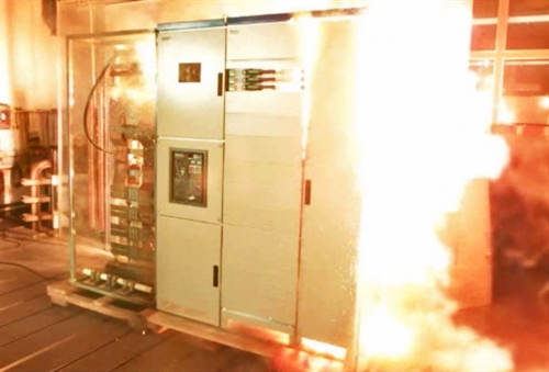
If you haven’t heard of all the effects of arc flash, there is a brief summary here.
Firstly, it’s important to know that “arc flash” is different to “arc fault”. The latter is loosely defined as low-energy electric arcs which occur mainly in low-voltage final circuits and may have prolonged duration. Arc faults mainly pose a danger due to their ability to start fires (see BS 7671:2018 clause 421.1.7) and have led to the development of Arc Fault Detection Devices (AFDDs) which are exclusive to single-phase final circuits. Arc flash is a higher-energy phenomenon, which presents a direct danger to equipment and personnel due to the energy released. Although when assessing your system it is important to consider both arc flash and arc fault phenomena, this article will focus only on arc flash.
Firstly, it’s important to know that “arc flash” is different to “arc fault”. The latter is loosely defined as low-energy electric arcs which occur mainly in low-voltage final circuits and may have prolonged duration. Arc faults mainly pose a danger due to their ability to start fires (see BS 7671:2018 clause 421.1.7) and have led to the development of Arc Fault Detection Devices (AFDDs) which are exclusive to single-phase final circuits. Arc flash is a higher-energy phenomenon, which presents a direct danger to equipment and personnel due to the energy released. Although when assessing your system it is important to consider both arc flash and arc fault phenomena, this article will focus only on arc flash.
Why is arc flash relevant in the UK?
This is a difficult question to answer since there is very little UK specific guidance on how to decide if arc flash might be a problem or what to do about it if it is. The two most relevant publications available at the time of writing are HSE guidance note HSG85 and the IET Wiring Regulations, Eighteenth Edition BS 7671:2018.
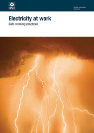
HSG85, “Electricity at work: Safe working practices” is available for free download here. In clause 5 it notes that arc flash may pose a risk to personnel but gives no advice on how it might be dealt with.

BS7671:2018, “Requirements for Electrical Installations” also notes that arcing poses a danger due to the pressure released and associated toxic gases, see clause 131.1 (VII). This publication is confusing since it has several references to arc faults or arc fault detection devices (clauses 421.1.7, 532.5 and 532.6) but never specifically mentions “arc flash” or “flashover” as it is sometimes known.
Given the lack of specific guidance, most companies in Europe use the USA standard IEEE 1584 for calculating the energy that could be released by an arc flash event and the degree of protection or separation distance personnel are likely to need to prevent harm.
Since there is no UK equivalent it can be hard to see how IEEE 1584 applies. However, it is generally accepted as a good means of fulfilling an employer’s duty of care over its employees.
Since there is no UK equivalent it can be hard to see how IEEE 1584 applies. However, it is generally accepted as a good means of fulfilling an employer’s duty of care over its employees.
Arc Flash Risk Assessments:
The first place to begin safeguarding your electrical facility is to conduct a risk assessment. Qualitatively, you should consider factors such as
- Precedents for arc flash incidents at your facility or similar facilities.
- Specific local hazards which might increase the severity of an arc flash incident; flammable materials stored nearby, proximity of local residents etc.
- Design and condition of electrical distribution and transmission equipment
A quantitative assessment of arc flash risks requires a more detailed understanding of your electrical system. Power system design software such as the Power*Tools for Windows software (PTW) can calculate the likely maximum amount of energy released during an electric arc and produce a recommendation for the level of Personal Protective Equipment (PPE) required to protect personnel and the safe working distance from affected electrical switchgear. These calculations are predominantly based on the USA standard IEEE 1584. CEE Relays Ltd has a great deal of experience in calculating arc flash energies on switchgear and can perform studies on your behalf, if required.
Although they are a starting point for arc flash protection, risk assessments should be revisited periodically and updated to reflect changes in your electrical system. These may include increased or reduced fault levels, changes to protection settings or other design changes. The arc flash standard IEEE 1584 has also recently changed to reflect measurements of arc flash energy released from switchgear of different designs. If you have previously calculated the maximum arc flash energy on your system, you may wish to consider re-calculating according to the updated standard using the latest version of PTW. For a brief summary of what has changed in IEEE 1584:2018, click here .
In the UK, HSG85 clause 29 requires companies of 5 or more employees to keep a written record of any hazards identified during risk assessments.
Reduce the arc flash risk:
Arc flash energy can be reduced by identifying and isolating arc flash currents more quickly. If arc flash is assessed to be a big problem on your system you may wish to employ arc detection systems. Alternatively, overcurrent relays and circuit breakers can be used to reduce arc energies by adding instantaneous elements or adjusting protection settings.

Note that changes to protection settings can have other, unwanted effects on your electrical system including poor discrimination, spurious tripping or limiting the number of pieces of equipment which may be used simultaneously.
PTW can be used to calculate all of these factors and help you to find the best compromise for your protection settings.

Depending on the design of your system it may not be possible to reduce the energy released during an arc flash to a level where the risk to personnel is considered low. The risk of arc flash should therefore be managed carefully.

Consider training, labelling electrical switchgear, providing PPE , operating restrictions, and other measures to protect personnel and equipment. PPE should always be considered as a last resort (or a backup, where other protective measures are in place).
If the danger cannot be eliminated then it may be possible instead to remove personnel from the vicinity of the danger by using remote switching systems. Likewise, operating restrictions are far safer if accompanied by interlock systems which physically prevent personnel from disobeying the restriction. For example, if live switching of a feeder is prohibited, the “trip” and “close” functions of the switching device can be inhibited using key lockouts or an inter-trip to isolate the feeder using an up-stream device.
Arc detection:
Fitting switchgear with arc detection systems does not reduce the likelihood of an arc flash event. However, arc detectors may reduce the energy released during an arc flash. The reason for this is that they may trip incoming power supplies very quickly and therefore extinguish the arc as soon as possible.
There are various types of arc detection systems available; most commonly they detect the bright lights produced by electric arcs but can also use combinations of overcurrent and pressure sensors to prevent spurious trips. Click here for details of the CEE arc detection systems. Arc detection systems are useful because they operate very quickly. The processing delay is minimal and there is little or no need to discriminate between devices. As soon as an arc is detected, a “trip” signal can be sent to one or more circuit breakers immediately.
There are various types of arc detection systems available; most commonly they detect the bright lights produced by electric arcs but can also use combinations of overcurrent and pressure sensors to prevent spurious trips. Click here for details of the CEE arc detection systems. Arc detection systems are useful because they operate very quickly. The processing delay is minimal and there is little or no need to discriminate between devices. As soon as an arc is detected, a “trip” signal can be sent to one or more circuit breakers immediately.
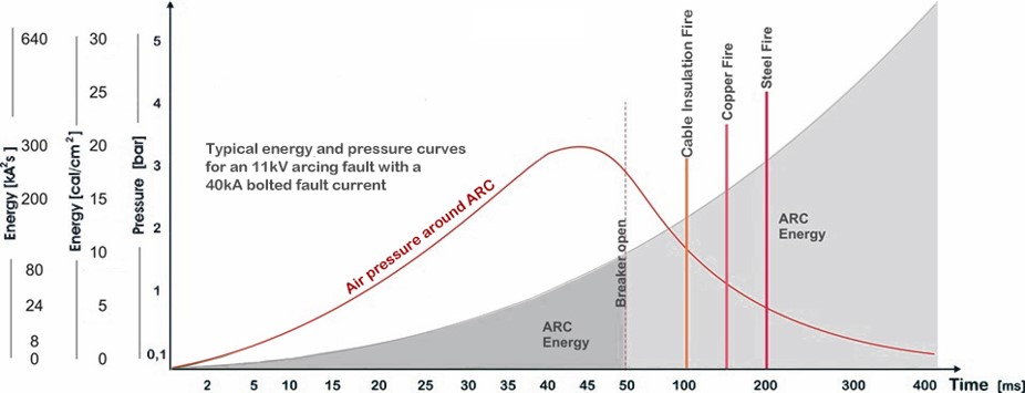
The limitation of arc detection systems linked to traditional switchgear is that the switchgear itself will have a minimum operating time (the example to the right assumes 50ms). Therefore there will be a minimum period for which an electric arc will continue to release energy; in some systems the resulting arc flash energy will still be unacceptably high.
Where drastic reductions in arc flash energy are required, arc detection systems can be linked to an arc quenching device. Arc quenching devices do not trip circuits in the traditional way; instead they couple the phase conductors of a system experiencing an arc directly to earth, while the normal circuit breakers are still operating. The earth connection re-directs the electrical energy to earth and away from the arc, which is extinguished. Arc quenchers operate in 3-5ms compared to 40-100ms for a traditional circuit breaker, therefore resulting in a vast reduction in arc flash energy released. Please contact us for more information about our reusable arc quencher
Labelling your electrical equipment:
Once an arc flash hazard has been identified, electrical switchgear and other large pieces of electrical equipment should be labelled to warn users. PTW can create printable warning labels automatically according to a template or to your own custom design. In the UK there are no specific guidelines for the design of warning labels although it is generally accepted that they should be clear, legible and include:
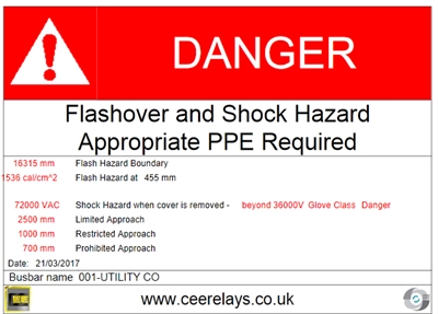
- Reference number for the equipment
- Maximum voltage applied to the equipment in normal operation
- The “incident energy” (maximum energy released during an arc flash)
- The minimum level of PPE required to operate the equipment or work in its vicinity. Even though it is no longer recommended by the NFPA, engineers still refer to levels of PPE on labels
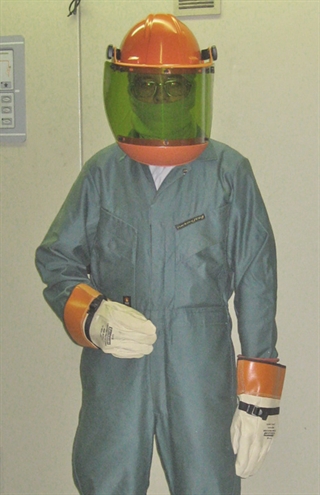
Personal protective equipment (PPE):
Ideally, PPE should be the last resort for protecting personnel when there are no other options for reducing the arc flash energy to which they could be exposed.
In the UK, HSG85 clause 32 suggests the use of PPE rated for protection against arc flash (referred to as “flashover”). There are no UK-specific standards for the design of arc flash rated clothing; the “Personal protective equipment at work” regulations make no mention of arc flash whatsoever. A guide to these regulations (HSE publication I25) is available for free download here.
In the European Union, Arc flash PPE should comply with European standard EN61482-1-2.
Note that the German accident insurance organisation (DGUV) has published its own guidance on the selection of PPE for protection against arc flash (available for free download here). However, this publication uses a completely different calculation method for determining the arc flash energy of electrical equipment and is really only useful for specifying PPE tested to German “VDE” standards.
It is common for PPE to be specified in “categories”; that is, upper and lower bounds of arc flash energy between which a particular type of PPE is acceptable. Work on or near equipment with low arc flash energy may require a much more basic form of PPE than work on apparatus with a risk of high arc flash energy.
In the UK there is no exact rule on the delineation between different categories of PPE; this is usually based on the types of PPE available. Some companies may choose to introduce a safety margin (for example, PPE rated at 40cal/cm2 may be used on equipment with an arc flash energy of no more than 32cal/cm2). PTW enables users to define the upper and lower bounds of their own PPE categories, including the arc energy level above which no type of PPE is considered sufficient.
In the UK there is no exact rule on the delineation between different categories of PPE; this is usually based on the types of PPE available. Some companies may choose to introduce a safety margin (for example, PPE rated at 40cal/cm2 may be used on equipment with an arc flash energy of no more than 32cal/cm2). PTW enables users to define the upper and lower bounds of their own PPE categories, including the arc energy level above which no type of PPE is considered sufficient.
Improve clearances around switchgear:
Clearances around switchgear do not inherently reduce the arc flash danger, since the greatest harm and highest likelihood of arc flash is generally when personnel are operating the switchgear. However, when the arc flash energy has been reduced as far as possible, some additional clearances may be required around the switchgear. Equipment which has a maximum arc flash energy low enough to be operated whilst using arc-rated PPE may need some clearances to:
PTW may estimate an Arc Flash Boundary, which is defined as distance from exposed live parts within which a person could receive a 2nd degree burn. This may in turn be useful in specifying clearances around switchgear (which may exceed the minimum required distance), although there is no specific legal requirement to use the calculated arc flash boundary as a clearance distance.
Switchgear for which the arc flash energy exceeds the maximum rating of any PPE may be operated remotely. In this circumstance, the arc flash boundary describes the area from which personnel should be excluded during switching operations.
For switchgear which is open to the air, the distance from the switchgear to the fence line or other barriers should be greater than the calculated arc flash boundary.
- Provide enough access space that nearby personnel who are not wearing arc-rated PPE may remain a safe distance from the switchgear when it is being used.
- Prevent, as far as possible, damage to adjacent switchgear or equipment if an arc flash were to occur.
PTW may estimate an Arc Flash Boundary, which is defined as distance from exposed live parts within which a person could receive a 2nd degree burn. This may in turn be useful in specifying clearances around switchgear (which may exceed the minimum required distance), although there is no specific legal requirement to use the calculated arc flash boundary as a clearance distance.
Switchgear for which the arc flash energy exceeds the maximum rating of any PPE may be operated remotely. In this circumstance, the arc flash boundary describes the area from which personnel should be excluded during switching operations.
For switchgear which is open to the air, the distance from the switchgear to the fence line or other barriers should be greater than the calculated arc flash boundary.
Where can I find guidance on calculations and risk assessments for arc flash in the UK?

If your company needs to prepare risk assessments, policies or strategies for managing arc flash in electrical systems, the most comprehensive guideline in the UK so far is published by the Energy Institute. The publication is “Assessing and managing the risk of arc flash”; details are to be found here. Within it you can find example risk assessments and an overview of all the different ways in which arc flash energy can be calculated and mitigated.
If you need to perform an arc flash study, create tailored warning labels for switchgear or re-visit your protection settings to reduce arc energies then CEE can help. Also consider our range of arc detection-based products to add an additional layer of safety to your system. Remember that arc flash should be a consideration for the design of new equipment as well as for pre-existing switchgear.
For an in-house solution, the PTW software can model the arc flash energies throughout your electrical distribution system. Build and maintain a model of your switchgear; update it with additions to your system and ensure that there has been no increase in arc flash energy. Note that PTW’s Arc Flash Evaluation module was recently updated according to the 2018 version of the IEEE 1584 standard. Existing users can find out how to upgrade their software here.